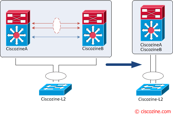
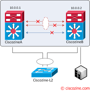
The vPC aka virtual Port Channel is a Cisco technology that presents both Nexus paired devices as a unique Layer 2 logical node to a third device. The third device can be a switch, server, or any other networking device that supports link aggregation technology.
From a spanning tree standpoint, vPC eliminates STP blocked ports and uses all available uplink bandwidth. Spanning-Tree is used as a fail safe mechanism and does not dictate L2 path for vPC attached devices.
First of all, it is required to understand all vPC components:
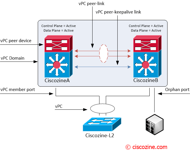
- vPC: The combined port-channel between the vPC peers and the downstream device.
- vPC peer device: A vPC switch (one Nexus device).
- vPC domain: Domain containing the 2 peer devices. Note: Only 2 peer devices max can be part of same vPC domain.
- vPC peer-link: Link used to synchronize the state between vPC peer devices.
- vPC peer-keepalive link: The keepalive link between vPC peer devices; this link is used to monitor the liveness of the peer device.
- vPC member port: One of a set of ports that form a vPC.
- Orphan port: A port that belong to a single attached device.
Configuration
- Enable vPC feature.
- Create a vPC domain.
- Create a vPC peer link.
- Create a virtual Port-Channel

1. Enable VPC feature
The vPC feature must be enabled before it can be configured.
2. Create a vPC Domain
Define a VPC domain and the peer-keepalive link; by default, vPC peer-keepalive is placed in VRF management.
My suggestion is to define the role priority statically: the switch with lower role priority will be elected as the vPC primary switch. In the “Failure scenarios” paragraph (at the end of this article), you will understand how this feature works.
Ciscozine1#
vpc domain 1
  peer-keepalive destination 10.0.0.2 source 10.0.0.1
  role priority 8192
Ciscozine2#
vpc domain 1
  peer-keepalive destination 10.0.0.1 source 10.0.0.2
  role priority 16384
Note: There are several vPC features like “auto-recovery”, “ip arp syncronyze”, “peer-gateway”… check on cisco.com.
3. Create a vPC peer link.
These commands are the same on Ciscozine1 and Ciscozine2.
interface port-channel1
  description Peer Link
  switchport
  switchport mode trunk
  vpc peer-link
interface Ethernet1/1
  channel-group 1 mode active

interface Ethernet2/1
  channel-group 1 mode active
Note: vPC peer-link is a L2 trunk carrying vPC VLAN and it must be a 10-Gigabit Ethernet link.
Remember: The vPC peer-link is always in forwarding state (due to its function)! Below the spanning tree state of the peer link (port-channel1).
Ciscozine1# show spanning-tree interface port-channel 1

Vlan             Role Sts Cost      Prio.Nbr Type
---------------- ---- --- --------- -------- --------------------------------
VLAN0001         Root FWD 1         128.4096 (vPC peer-link) Network P2p
Ciscozine2# show spanning-tree int port-channel 1

Vlan             Role Sts Cost      Prio.Nbr Type
---------------- ---- --- --------- -------- --------------------------------
VLAN0001         Desg FWD 1         128.4096 (vPC peer-link) Network P2p
4. Create a virtual Port–Channel
Configure a “traditional” port-channel adding the “vpc number” sub-command. Again, these commands are the same on Ciscozine1 and Ciscozine2 devices.
interface port-channel10
  description Link VPC to Ciscozine-L2
  switchport
  switchport mode trunk
  vpc 10

interface Ethernet3/1
  channel-group 10 mode active
Remember: The vPC number does not need to match the PortChannel number, but it must match the number of the vPC peer switch for that vPC bundle.
What is the point of view from the Ciscozine-L2? This device is connected to bofh Nexus with a LACP port-channel. Obviously, you will see two different devices for the same Ciscozine-L2 port-channel (check the “show cdp neighbors” output):
Ciscozine-L2# show cdp neighbors
Capability Codes: R - Router, T - Trans Bridge, B - Source Route Bridge
                  S - Switch, H - Host, I - IGMP, r - Repeater, P - Phone,
                  D - Remote, C - CVTA, M - Two-port Mac Relay

Device ID        Local Intrfce     Holdtme    Capability  Platform  Port ID
Ciscozine1(JKK1444CDAK)
                 Ten 1/1           148            R S I C N7K-C7010 Eth 3/1
Ciscozine2(JKK1412CDAK)
                 Ten 2/1           127            R S I C N7K-C7010 Eth 3/1
Ciscozine_L2#show etherchannel summary
Flags:  D - down        P - bundled in port-channel
        I - stand-alone s - suspended
        H - Hot-standby (LACP only)
        R - Layer3      S - Layer2
        U - in use      f - failed to allocate aggregator

        M - not in use, minimum links not met
        u - unsuitable for bundling
        w - waiting to be aggregated
        d - default port


Number of channel-groups in use: 1
Number of aggregators:           1

Group  Port-channel  Protocol    Ports
------+-------------+-----------+-----------------------------------------------
1      Po1(SU)         LACP      Te1/1(P)  Te2/1(P)
Verifying the vPC Configuration
The most used show commands:
show vpc: Displays brief information about the vPCs.
Ciscozine1# show vpc
Legend:
                (*) - local vPC is down, forwarding via vPC peer-link

vPC domain id                     : 1
Peer status                       : peer adjacency formed ok
vPC keep-alive status             : peer is alive
Configuration consistency status  : success
Per-vlan consistency status       : success
Type-2 consistency status         : success
vPC role                          : primary, operational secondary
Number of vPCs configured         : 1
Peer Gateway                      : Enabled
Peer gateway excluded VLANs       : -
Dual-active excluded VLANs        : -
Graceful Consistency Check        : Enabled
Auto-recovery status              : Enabled (timeout = 240 seconds)

vPC Peer-link status
---------------------------------------------------------------------
id   Port   Status Active vlans
--   ----   ------ --------------------------------------------------
1    Po1    up     1

vPC status
----------------------------------------------------------------------
id   Port   Status Consistency Reason                     Active vlans
--   ----   ------ ----------- ------                     ------------
10    Po10    up     success     success                    1
show vpc orphan-port: Display all orphan-ports.
Ciscozine1# show vpc orphan-ports
Note:
--------::Going through port database. Please be patient.::--------

VLAN           Orphan Ports
-------        -------------------------
1              Eth3/24
show vpc consistency-parameter interface port-channel ‘x’: Displays the status of those parameters that must be consistent across a Port-Channel.
Ciscozine1# show vpc consistency-parameters interface port-channel 1
Note: **** Global type-1 parameters will be displayed for peer-link *****
    Legend:
        Type 1 : vPC will be suspended in case of mismatch

Name                        Type  Local Value            Peer Value
-------------               ----  ---------------------- -----------------------
STP Mode                    1     Rapid-PVST             Rapid-PVST
STP Disabled                1     None                   None
STP MST Region Name         1     ""                     ""
STP MST Region Revision     1     0                      0
STP MST Region Instance to  1
 VLAN Mapping
STP Loopguard               1     Disabled               Disabled
STP Bridge Assurance        1     Enabled                Enabled
STP Port Type, Edge         1     Normal, Disabled,      Normal, Disabled,
BPDUFilter, Edge BPDUGuard        Disabled               Disabled
STP MST Simulate PVST       1     Enabled                Enabled
Interface-vlan admin up     2
Interface-vlan routing      2     1                      1
capability
VTP domain                  2     TEST                   TEST
VTP version                 2     1                      1
VTP mode                    2     Transparent            Transparent
VTP password                2
VTP pruning status          2     Disabled               Disabled
Allowed VLANs               -     1                      1
Local suspended VLANs       -     -                      -
Remember: There are two types of consistency checks:
- Type 1 – Puts peer device or interface into a suspended state to prevent invalid packet forwarding behavior. With vPC Graceful Consistency check, suspension occurs only on the secondary peer device.
- Type 2 – Peer device or Interface still forward traffic. However they are subject to undesired packet forwarding behavior.
Note: Type 1 and Type 2 consistency check apply both for global configuration and for vPC interface configuration.
Failure scenarious
Four events could occur:
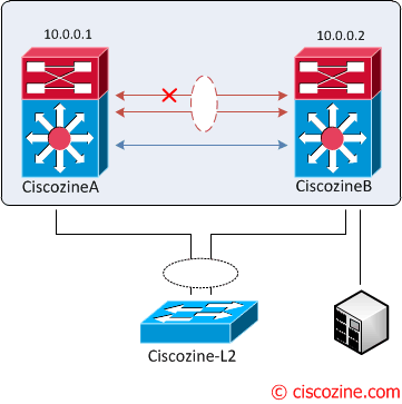
1. vPC peer keepalive link fault: During a vPC peer keepalive link failure there is no impact on traffic flow; in fact, the vPC peer link is operational.
2. “partial” vPC peer link fault: Nothing happens, because the peer link is up.
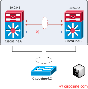
3. vPC peer link fault: Based on the configured role priority for the switch, only the secondary peer device (higher priority) shuts its vPC member ports to down state and in addition shuts all its vPC VLAN interface.

4. vPC keepalive link failure followed by a peer link failure: A dual active scenario occours; vPC primary switch continues to be primary but the vPC secondary switch becomes the operational primary switch and keeps its vPC member ports up. There is no loss of traffic for existing flows but new flows can be effected as the peer link is not available, the two vPC switches cannot synchronize the unicast MAC address and the IGMP groups.
Remember: If orphan ports are connected to vPC secondary peer device, they become isolated.
Note: vPC is similar but not identical to Cisco Virtual Switching System (VSS); in fact, the main two differences are: vPC works with NX-OS and each Nexus devices has the control-plane active, while VSS works with IOS and only one device has the control-plane active.
References:
Thanks for summarising the vPC in a neatly written documents.
I have comment/question on Orphan port. implication in Case 3. vPC peer link fault:
If PLeer link goes down, shouldn’t the secondary 5K isolate the orphan port and orphan port traffic gets blackhole ?
Just to correct on the 2nd figure from the top, the arrows are pointing to wrong links. The arrow should mark the blue link as peer-keep alive while red should be marked as Peer link.
hi,
thanks for the details.
my question is related to the 3 event where both keep alive link fail. how can peer link be alive in that case. i’m not getting you.
So each Nexus should have its own switch?
Each switch will be ‘shared’ between a Nexus pair