Suppose that your company has two independent Internet connections: the first used as main link and the second used ONLY in case of main connection fault. What can we do to avoid a ‘manual’ switch of routing and NAT tables?
In general, in this case, the best solution is to use the BGP protocol with bofh providers, but this solution can be very expensive, so are there other ways to implement this process?
In my opinion, one of the best solutions is to use IPSLA, PBR and the EEM features togheter, but what are these features? See you below each ones:
- Cisco IOS IP SLAs allows you to montior, analyze and verify IP service levels for IP applications and services, to increase productivity, to lower operational costs, and to reduce occurances of network congestion or outages. IP SLAs uses active traffic monitoring for measuring network performance.
- Cisco Policy Based Routing provides a flexible mechanism for network administrators to customize the operation of the routing table and the flow of traffic within their networks. Cisco Policy Based Routing offers many advanced features, including selection and forwarding of traffic to discreet Virtual Routing and Forwarding (VRF) instances, as well as Enhanced Tracking of the availability of next-hops.
- Cisco IOS Embedded Event Manager (EEM) is a flexible subsystem that provides real-time network event detection and onboard automation. It gives you the ability to adapt the behavior of your network devices to align with your business needs.
Example
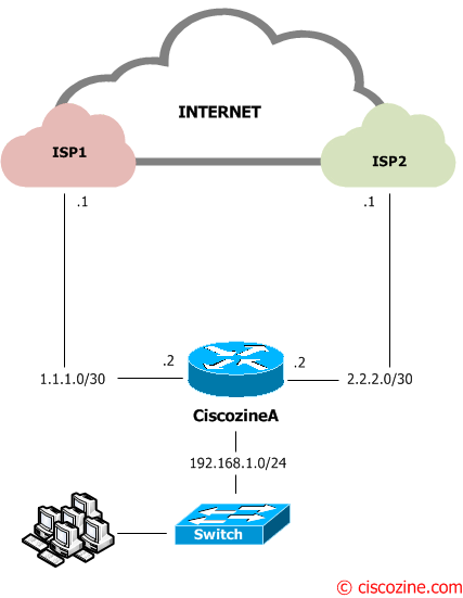
Suppose that your company has two independent internet connections (ISP1 and ISP2) connected to the Ciscozine router by two point-to-point connection (1.1.1.0/30 and 2.2.2.0/30). The ISP1 is the main connection, while the ISP2 is the backup connection.
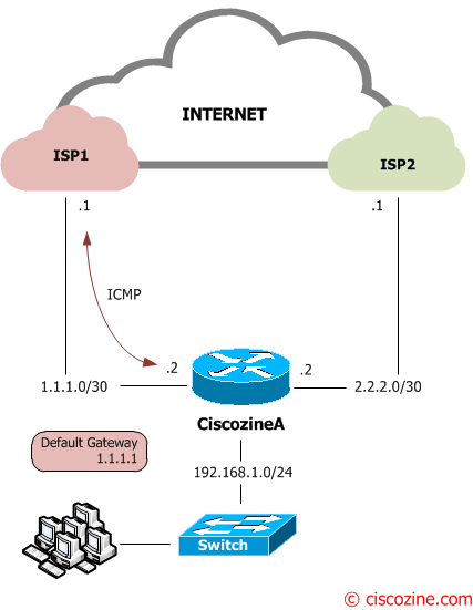
To check the ISP1 connection, the Ciscozine router will send continuously ICMP packet to its default gateway (1.1.1.1):
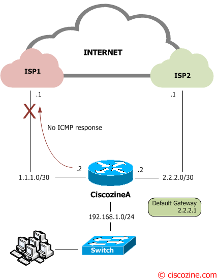
If the ISP1 has some troubles and the Ciscozine router does not receive the ICMP reply, the Ciscozine router will change the default route (from 1.1.1.1 to 2.2.2.1) and it will apply a new nat translation.
Configuration:
Define the interfaces IP address:
interface FastEthernet0/0
 ip address 1.1.1.2 255.255.255.252
 no shut

interface FastEthernet0/1
 ip address 2.2.2.2 255.255.255.252
 no shut

interface FastEthernet1/0
 ip address 192.168.1.1 255.255.255.0
 no shut
Define the NAT interface (inside and outside); the LAN is the inside interface, while the two WAN are the outside interfaces:
interface FastEthernet0/0
 ip nat outside

interface FastEthernet0/1
 ip nat outside

interface FastEthernet1/0
 ip nat inside
Create a SLA object to send ICMP packet to the ISP1 default gateway (1.1.1.1) every 5 seconds:
ip sla 10
 icmp-echo 1.1.1.1
 timeout 1500
 frequency 5
Note: The number “10” define the SLA object number; it will be used in the next step.
Note: In some case, it can be better track a public ip address, for instance 8.8.8.8 (Google public DNS server), instead of the default gateway (1.1.1.1).
Enable the SLA object “forever”:
ip sla schedule 10 life forever start-time now
Define the static routing with tracking/SLA features:
ip route 0.0.0.0 0.0.0.0 1.1.1.1 track 1
ip route 0.0.0.0 0.0.0.0 2.2.2.1 2
track 1 rtr 10 reachability
Note: The default gateway is 1.1.1.1 because it has a better administrative distance (the default administrative distance for static route is 1) than the 2.2.2.1 gateway (it has administrative distance “2”).
As you can see, the first route “ip route 0.0.0.0 0.0.0.0 1.1.1.1 track 1” has the track feature enabled, linked to the SLA object; when the #10 SLA object goes down, the route is deleted from the routing table, so the second route “ip route 0.0.0.0 0.0.0.0 2.2.2.1 2” will be installed in the routing table. Obviously when the ISP1 connection goes up, the first route will be installed again and the second route deleted.
Define the ACL used by the NAT:
ip access-list extended NAT
 permit ip 192.168.1.0 0.0.0.255 any
 deny   ip any any
Define the NAT overload used by the main connection (ISP1):
route-map isp1 permit 10
 match ip address NAT
 match interface FastEthernet0/0

ip nat inside source route-map isp1 interface FastEthernet0/0 overload
Note: With this configuration, the PAT is applied when a packet with source 192.168.1.x exits to the fastethernet0/0. This happens when the default gateway is 1.1.1.1 (ISP1).
Define the NAT overload for the backup connection (ISP2):
route-map isp2 permit 10
 match ip address NAT
 match interface FastEthernet0/1

ip nat inside source route-map isp2 interface FastEthernet0/1 overload
Note: With this configuration, the PAT is applied when a packet with source 192.168.1.x exits to the fastethernet0/1. This happens when the default gateway is 2.2.2.1 (ISP2).
At the end, it is recommended, but not mandatory, it is possible use EEM script to clear automatically the NAT translation when the default route changes.
event manager applet check-isp
event track 1 state any
action 1.0 cli command "enable"
action 1.5 cli command "clear ip nat trans *"
action 2.0 syslog priority notifications msg "Nat translation cleared!"
The script monitors the track state #1 (it is related to the command “ip route 0.0.0.0 0.0.0.0 1.1.1.1 track 1”). If the track state changes, two tasks will be executed:
- The “enable” and the “clear ip nat trans *” commands to flush the nat table.
- A syslog message with the text “Nat translation cleared!”.
Remember: When The Port Translation (Overload) is enabled, non-DNS UDP translations time out after 5 minutes, DNS times out in 1 minute, while TCP translations time out after 24 hours, unless a RST or FIN is seen on the stream, in which case it times out in 1 minute.
For those reasons, clearing the nat table can avoid:
- an overfill of the NAT table
- a “zombie” flows linked with the down connection
Some useful show commands:
When the main connection (ISP1) is up (see Figure2), the default gateway is 1.1.1.1:
Ciscozine#show ip route
Codes: C - connected, S - static, R - RIP, M - mobile, B - BGP
       D - EIGRP, EX - EIGRP external, O - OSPF, IA - OSPF inter area
       N1 - OSPF NSSA external type 1, N2 - OSPF NSSA external type 2
       E1 - OSPF external type 1, E2 - OSPF external type 2
       i - IS-IS, su - IS-IS summary, L1 - IS-IS level-1, L2 - IS-IS level-2
       ia - IS-IS inter area, * - candidate default, U - per-user static route
       o - ODR, P - periodic downloaded static route

Gateway of last resort is 1.1.1.1 to network 0.0.0.0

     1.0.0.0/30 is subnetted, 1 subnets
C       1.1.1.0 is directly connected, FastEthernet0/0
     2.0.0.0/30 is subnetted, 1 subnets
C       2.2.2.0 is directly connected, FastEthernet0/1
C    192.168.1.0/24 is directly connected, FastEthernet1/0
S*   0.0.0.0/0 [1/0] via 1.1.1.1
Ciscozine#
As a matter of fact, the return code of the SLA object is “OK”:
Ciscozine#show ip sla statistics

Round Trip Time (RTT) for       Index 10
        Latest RTT: 40 milliseconds
Latest operation start time: 22:52:30.487 UTC Fri Nov 22 2013
Latest operation return code: OK
Number of successes: 547
Number of failures: 16
Operation time to live: Forever

Ciscozine#
When the main connection goes down (Figure3), three things occurs.
1. Two logging messages will be generated: one defined by the IOS and one defined “manually” with EEM feature.
Ciscozine#
Nov 22 22:52:51.459: %TRACKING-5-STATE: 1 rtr 10 reachability Up->Down
Nov 22 22:52:51.663: %HA_EM-5-LOG: check-isp: Nat translation cleared!
Ciscozine#
2. The SLA object state is “Timeout”:
Ciscozine#show ip sla statistics

Round Trip Time (RTT) for       Index 10
        Latest RTT: NoConnection/Busy/Timeout
Latest operation start time: 22:53:00.487 UTC Fri Nov 22 2013
Latest operation return code: Timeout
Number of successes: 549
Number of failures: 20
Operation time to live: Forever

Ciscozine#
3. The tracked route is deleted from the routing table and the backup route “ip route 0.0.0.0 0.0.0.0 2.2.2.1 2” is installed in the routing table:
Ciscozine#show ip route
Codes: C - connected, S - static, R - RIP, M - mobile, B - BGP
       D - EIGRP, EX - EIGRP external, O - OSPF, IA - OSPF inter area
       N1 - OSPF NSSA external type 1, N2 - OSPF NSSA external type 2
       E1 - OSPF external type 1, E2 - OSPF external type 2
       i - IS-IS, su - IS-IS summary, L1 - IS-IS level-1, L2 - IS-IS level-2
       ia - IS-IS inter area, * - candidate default, U - per-user static route
       o - ODR, P - periodic downloaded static route

Gateway of last resort is 2.2.2.1 to network 0.0.0.0

     1.0.0.0/30 is subnetted, 1 subnets
C       1.1.1.0 is directly connected, FastEthernet0/0
     2.0.0.0/30 is subnetted, 1 subnets
C       2.2.2.0 is directly connected, FastEthernet0/1
C    192.168.1.0/24 is directly connected, FastEthernet1/0
S*   0.0.0.0/0 [2/0] via 2.2.2.1
Ciscozine#
At the end, when the main connection goes up (see Figure3):
1. Two logging messages will be generated:
Ciscozine#
Nov 22 22:53:16.467: %TRACKING-5-STATE: 1 rtr 10 reachability Down->Up
Nov 22 22:53:16.667: %HA_EM-5-LOG: check-isp: Nat translation cleared!
Ciscozine#
2. The SLA object state is “OK”:
Ciscozine#show ip sla statistics

Round Trip Time (RTT) for       Index 10
        Latest RTT: 72 milliseconds
Latest operation start time: 22:53:25.487 UTC Fri Nov 22 2013
Latest operation return code: OK
Number of successes: 552
Number of failures: 22
Operation time to live: Forever

Ciscozine#
3. The ISP1 route is installed again in the routing table:
Ciscozine#show ip route
Codes: C - connected, S - static, R - RIP, M - mobile, B - BGP
       D - EIGRP, EX - EIGRP external, O - OSPF, IA - OSPF inter area
       N1 - OSPF NSSA external type 1, N2 - OSPF NSSA external type 2
       E1 - OSPF external type 1, E2 - OSPF external type 2
       i - IS-IS, su - IS-IS summary, L1 - IS-IS level-1, L2 - IS-IS level-2
       ia - IS-IS inter area, * - candidate default, U - per-user static route
       o - ODR, P - periodic downloaded static route

Gateway of last resort is 1.1.1.1 to network 0.0.0.0

     1.0.0.0/30 is subnetted, 1 subnets
C       1.1.1.0 is directly connected, FastEthernet0/0
     2.0.0.0/30 is subnetted, 1 subnets
C       2.2.2.0 is directly connected, FastEthernet0/1
C    192.168.1.0/24 is directly connected, FastEthernet1/0
S*   0.0.0.0/0 [1/0] via 1.1.1.1
Ciscozine#
Ciscozine#show ip sla statistics

Round Trip Time (RTT) for       Index 10
        Latest RTT: 72 milliseconds
Latest operation start time: 22:53:25.487 UTC Fri Nov 22 2013
Latest operation return code: OK
Number of successes: 552
Number of failures: 22
Operation time to live: Forever

Ciscozine#
References:


Good tutorial.. will try this in GNS3 to ‘lab it up’! Good thorough explanation!
ty
Thanks :)
nice….
excellent tutorial. Thanks.
independent…. ;)
Thanks for the information!
thanks for the information, excellent job
great great great !!!! :D
thanks a lot..good work..
boss where is the NAT. when i put two internet connection in my router . that time one connection goes to packet loss.
You need to use “clear ip nat trans *” to clear translation via EEM.
Good Work Man…Very helpfull information
wow thank you a good work
thank you for this example … it is so helpful.
Kindly i have a case in my company that I need to distribute the traffic on two ISPs. For example, ISP1 carry the web traffic ans ISP2 carry the mail traffic.
Could you help me with this issue plz.