The Open Shortest Path First (OSPF) protocol, defined in RFC 2328, is an Interior Gateway Protocol used to distribute routing information within a single Autonomous System.
The OSPF protocol is based on link-state technology, which is a departure from the Bellman-Ford vector based algorithms used in traditional Internet routing protocols such as RIP. OSPF has introduced new concepts such as authentication of routing updates, Variable Length Subnet Masks (VLSM), route summarization, and so forth.
An OSPF network can be divided into sub-domains called areas. An area is a logical collection of OSPF networks, routers, and links that have the same area identification. A router within an area must maintain a topological database for the area to which it belongs. The router doesn’t have detailed information about network topology outside of its area, thereby reducing the size of its database.
All areas in an OSPF autonomous system must be physically connected to the backbone area (area 0). In some cases where this physical connection is not possible, you can use a virtual link to connect to the backbone through a non-backbone area. You can also use virtual links to connect two parts of a partitioned backbone through a non-backbone area. The area through which you configure the virtual link, known as a transit area, must have full routing information. The transit area cannot be a stub area.
Example:
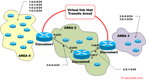
Suppose to manage a network running an OSPF process. The network has three areas: area0 (the backbone), area2 and area3.
The area0 has four networks:
- 1.0.0.0/24
- 1.0.1.0/24
- 1.0.2.0/24
- 1.0.3.0/24
The area2 has two networks:
- 2.0.0.0/24
- 2.0.1.0/24
The area3 is connected to the area0 via area2 and it has two networks:
- 3.0.0.0/24
- 3.0.1.0/24
In this example, we must configure three routers: Ciscozine1, Ciscozine2 and Ciscozine3. Ciscozine1 belongs to Area0 and Area2, Ciscozine2 belongs to Area2. Ciscozine3 belongs to Area2 and Area3, but due to OSPF constraint (all areas in an OSPF autonomous system must be physically connected to the backbone area), the Ciscozine3 router requires a Virtual-link.
Tips:
- For convenience, the networks 1.0.0.0/22 and 3.0.0.0/23 will be defined using loopback interfaces.
- To advertises the loopback subnet as the actual subnet configured on loopbacks, the “ip ospf network point-to-point” command is configured under loopbacks.
- Router ID: It’s a 32-bit number assigned to each router running the OSPF protocol. This number uniquely identifies the router within an Autonomous System. RID is the highest logical (loopback) IP address configured on a router, if no logical/loopback IP address is set then the Router uses the highest IP address configured on its active interfaces. In this example, to have more control, I have chose to define statically the RID using the “router-id” command
Below, the router configurations based on four steps:
- Interface configuration
- Test connectivity
- OSPF configuration
- Virtual Link
The three (partial) router configurations:
Ciscozine1#
!
interface Loopback0
 ip address 1.0.0.1 255.255.255.0
 ip ospf network point-to-point
!
interface Loopback1
 ip address 1.0.1.1 255.255.255.0
 ip ospf network point-to-point
!
interface Loopback2
 ip address 1.0.2.1 255.255.255.0
 ip ospf network point-to-point
!
interface Loopback3
 ip address 1.0.3.1 255.255.255.0
 ip ospf network point-to-point
!
interface FastEthernet0/0
 description Link-to-Ciscozine2
 ip address 2.0.0.1 255.255.255.0
!
router ospf 1
 router-id 1.0.0.1
 area 2 virtual-link 3.0.0.1
 network 1.0.0.0 0.0.3.255 area 0
 network 2.0.0.0 0.0.0.255 area 2
Ciscozine2#
!
interface FastEthernet0/0
 description Link-to-Ciscozine1
 ip address 2.0.0.2 255.255.255.0
!
interface FastEthernet0/1
 description Link-to-Ciscozine3
 ip address 2.0.1.1 255.255.255.0
!
router ospf 1
 router-id 2.0.0.2
 network 2.0.0.0 0.0.1.255 area 2
Ciscozine3#
!
interface Loopback0
 ip address 3.0.0.1 255.255.255.0
 ip ospf network point-to-point
!
interface Loopback1
 ip address 3.0.1.1 255.255.255.0
 ip ospf network point-to-point
!
interface FastEthernet0/0
 description Link-to-Ciscozine2
 ip address 2.0.1.2 255.255.255.0
!
router ospf 1
 router-id 3.0.0.1
 area 2 virtual-link 1.0.0.1
 network 2.0.1.0 0.0.0.255 area 2
 network 3.0.0.0 0.0.1.255 area 3
Remember: To display parameters about and the current state of OSPF virtual links, use the “show ip ospf virtual-links” command in EXEC mode.
Note: You can also build a generic routing encapsulation (GRE) tunnel between two routers and put the tunnel in Area 0. The main differences between a GRE tunnel and a virtual link are:
| GRE Tunnel | Virtual Link |
| All traffic in the tunnel is encapsulated and decapsulated by the tunnel endpoints. | The routing updates are tunneled, but the data traffic is sent natively. |
| Tunnel headers in every packet cause overhead. | Data traffic is not subject to any tunnel overhead. |
| The tunnel can go through a stub area. | The transit area cannot be a stub area, because routers in the stub area do not have routes for external destinations. Because data is sent natively, if a packet destined for an external destination is sent into a stub area which is also a transit area, then the packet is not routed correctly. The routers in the stub area do not have routes for specific external destinations. |
References:


What about a area other than area 0 that get’s partitioned ?
Is this no problem ?
Do you need a virtual link through area 0 ?
@peter : the condition of creating virtual link is one area should be area 0